LogicSim

Gamma Logic Gate Simulation

Wait a minute. Is gamma not a thing? You have alphas, then betas. So my first proper release will be named gamma. Deal with it.

Anyhow, I've cleaned up the simulator a lot since last time. There are a ton of new checks, and some new features, too. Inputs, for instance, will remain associated with Outputs even if a second output is dragged through the binding area.

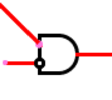
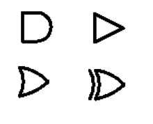
As far as new features, the simulator now includes grid spacing (Gates jump to line up with each other, so you get pretty right angles). By default, Gates are 30 pixels across. Setting their inputs to be 1/4 of that height apart from each other allows for a grid spacing of 7.5 pixels. There are a few modes: by default, a grid's drawn, and grid spacing is enforced. The grid and spacing can both be disabled, though, for a cleaner mode (no grid drawn) and a freeform one (no spacing enforced).
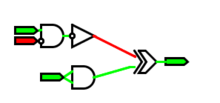
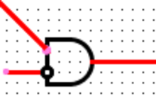
Wires!

One bug down!

I had Gates reassociate their hotspots whenever the gate moved. I also reassociated hotspots whenever they were moved. Problem is, Hotspots are placed relative to Objects, so they never move. The exception is the tail end of the wire. So, the Hotspot on the wire's tail associated fine, but the one connected to the head was never told to reassociate, so it would never connect to anything. Adding a few lines to tell the head to associate too worked perfectly.

Wires are now bidirectional and working!

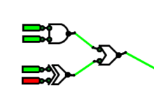
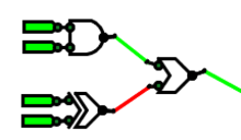
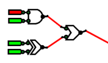
Working simulation!

This year, in digital circuits, I learned about digital circuits. Surprise. This year in CS, I learned about subclassing, data structures, and program flow. Together, I made a logic simulator.

Fundamentally speaking, digital circuits are made up of discrete components. Ganged together, these simple components are capable of realizing complex tasks.

Beta Logic Gate Simulation

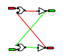
This weekend, I decided to throw out my previous logic simulator and make a new one based on what I'd learned. It's still in beta, but I got it to simulate an SR latch, and I'm proud. I'm going to sleep now, but wanted to tell the world about my success. Latches are awesome.

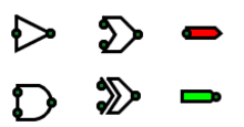
Reading this diagram: Red is false, green is true. The triangles are inverters; the blazes are OR gates (I'll pretty them up later). The flags on the right are inputs; the flags on the left are outputs. The green circles are inputs and outputs - the points where gates associate with each other. They're only shown for debugging.

More later. I promise.

Alpha Logic Gate Simulation

In ECE211 (that's Digital Circuits I, for those of you who don't go to Lafayette), we've been working with digital circuits. Surprising, right?

I was frustrated that I needed to draw out these complicated circuits by hand, and that the paper never gave me any helpful feedback. So I decided to write a logic gate simulator, using my favorite language for graphics, Processing.