By Ben Nitkin on

This year, in digital circuits, I learned about digital circuits. Surprise. This year in CS, I learned about subclassing, data structures, and program flow. Together, I made a logic simulator.
Fundamentally speaking, digital circuits are made up of discrete components. Ganged together, these simple components are capable of realizing complex tasks.
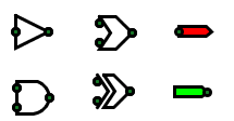
Simply put, a logic gate takes some boolean inputs, compares them to each other, and creates some outputs. For instance:
- AND gates output true when all of inputs are true
- OR gates will output true if at least one input is true
- XOR gates output true if an even number of inputs are true
- NOT gates output the inverse of the input.
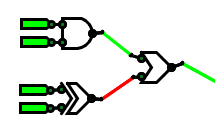
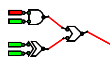
More complicated circuits can be built out of individual gates. The SR latch in the previous post is just two NOT's and two OR's. It has two inputs, Set and Reset. A momentary pulse on the Set input results in a persistent true signal on the Q output. Similarly, pulsing Reset makes Q persistently false.
Simple circuits are easy to simulate mentally. Problem is, when you get to more complicated circuits with feedback (like SR latches and flip flops), mental simulation becomes difficult or impossible. Additionally, sketching these circuits by hand is a pain: you can't rearrange the circuit, and I'm terrible at drawing neatly.
I decided to solve both problems at once. Months ago, you saw my first attempt at creating a logic simulation program. Problem was, I didn't think through the architecture well enough. With processing, placing gates on the canvas is child's play. But how do you connect them?
Inputs and outputs of gates are similar, but not identical: inputs can accept only one wire, while outputs can fork as many wires as desired. In the first version, I didn't know how to make inputs, or how to associate gates with each other, or how to represent wires, or when to try and associate inputs and outputs. (Reevaluating every link every frame is needlessly heavy on the processor.)
But that first version gave me a better idea of the challenge I faced, so my second attempt is much cleaner, and includes a reasonable structure.
The fundamental building block of the simulation is the Object. Objects have an x and y coordinate, a size, some number of inputs and outputs (yes, zero is a number), a draw method for display, and a tick method to simulate a single nanosecond. Objects also have hook functions that echo mouse events from the main loop to the object, provided that the object is close to the mouse. All Objects live in a central list - things - that is iterated over when drawing, ticking, and so on.
Object has a few subclasses: Gates, user inputs and outputs, Wires, Hotspots, and more complicated circuits.
Gate contains the common functionality of logic gates. By default, gates have two inputs and an output, a method that determines the ideal output of the state. When the ideal output changes, the gate waits for a number of ticks to pass to simulate propogation delay, then changes the output.
UserInput and UserOutput are very simple. UserInput outputs a true or false value, toggling when clicked. It's used to set the state of the system. UserOutput is just a flag that shows the state of the point it's attached to.
Wires have an input and an output, and simply set their output to their input's value every tick. Long chains of wires incur some delays, as they need more than one tick to carry a value all the way across.
Hotspots are the magical communication lines. Hotspot has two subclasses: Input and Output (not to be confused with UserInput and UserOutput). All hotspots include a get method to grab their current state. Opposite-clicking them toggles inversion. An set of abstract functions provides for automatic association, attachment, and detachment from other Hotspots. Output actually stores a value. It defines a set method for setting the net it's in to a boolean. Outputs also maintain a list of associated Inputs. Input simply inherits the state of its output, and can only attach to a single output.
ECE aside: If the input of a gate is connected to two wires, and those wires happen to disagree (one true; one false), bad things happen. The logic gates providing voltage upstream fight each other as they try and adjust the voltage up or down. They'll almost certainly be driven past specs. Best case, the circuit doesn't work. Worst case, some magic smoke escapes.
Whenever a Hotspot is moved, it tries to associate with nearby Hotspots. If any that it's attached to move out of range, they detach. And new Hotspots that come in range are attached.
I'll be able to code more complicated parts, like clocks and latches later. As of now, the program will simulate simple logic, so the next step is tidying and cleanup. Slated features include:
- More selective UserInputs: smaller hotspot for toggling
- Prettier gates: arcs for the OR's
- Bidirectional wires: right now, wires are directional. They have an input and an output end.
- Prettier jumpers: black jumpers are drawn between associated Hotspots. Wires should just jump to Gates, and linked gates should color their jumpers.
- Working wires: the input end of wires won't associate with other Hotspots, but other Hotspots will connect to it. There's a bug to be teased out.
- Grid spacing: force all gates to align to a 10px grid, for straight lines
- GUI: select gates from a dialog instead of using hotkeys like 'a' for AND.
- Savefiles
- Screenshots
As always code is below. Until next time!